The section describes how the building hardware components should be connected together to form a fully functional CORD POD.
Management / control-plane network
The management network is divided in two broadcast domains: one connecting the POD to the Internet and giving access to the deployer, called “external” and shown in green in the diagram below; one called “internal” or “management”, in blue. The diagram also reports for completeness data-plane connections in red, which will be covered in the next paragraph.
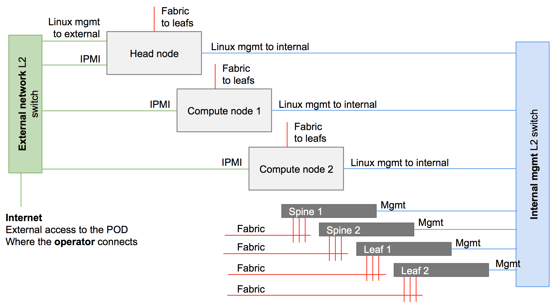
The external and the management networks can be separated either using two different switches, or the same physical switch and using VLANs.
Head node IPMI connectivity is optional.
IPMI ports do not have to be necessarily connected to the external network. The requirement is that compute node IPMI interfaces need to be reachable from the head node. This is possible also -for example- through the internal / management network.
Often, vendors allow to use a shared management port to provide IPMI functionalities. One of the NICs used for system management (called eth0 for example in the operating system) can be shared, to be used at the same time also as IPMI port
The external network
The external network allows the POD to go to the Internet, and operators to access the POD. Usually, operators want to be able to directly start/stop/reboot the head and the compute nodes from this network. Moreover, using CORD automated scripts and tools for Jenkins pipeline requires Jenkins direct access to these interfaces. This is why IPMI/BMC interfaces of the nodes are also connected to the external network.
In summary, following is the list of equipment/interfaces usually connected to the external network:
Internet
Dev machine
Head node - 1x 1G interface (following defined as external)
Head node - 1x IPMI/BMC interface (optional)
Compute node 1 - 1x IPMI/BMC interface (optional, strongly suggested for a proper CORD installation)
Compute node 2 - 1x IPMI/BMC interface (optional, strongly suggested for a proper CORD installation)
The internal network
The internal/management network is separate from the external one. It has the goal to connect the head node to the rest of the system components (compute nodes and fabric switches).
Usually, for a typical POD, the internal network includes:
Head node - 1x 1G interface (following defined as management)
Compute node 1 - 1x 1G interface
Compute node 2 - 1x 1G interface
Fabric 1 - management interface
Fabric 2 - management interface
Fabric 3 - management interface
Fabric 4 - management interface
User / data-plane network
The data-plane network -represented in red in the picture- is the one carrying the user traffic (in green), from the access devices till the end of the POD connected to the metro network.
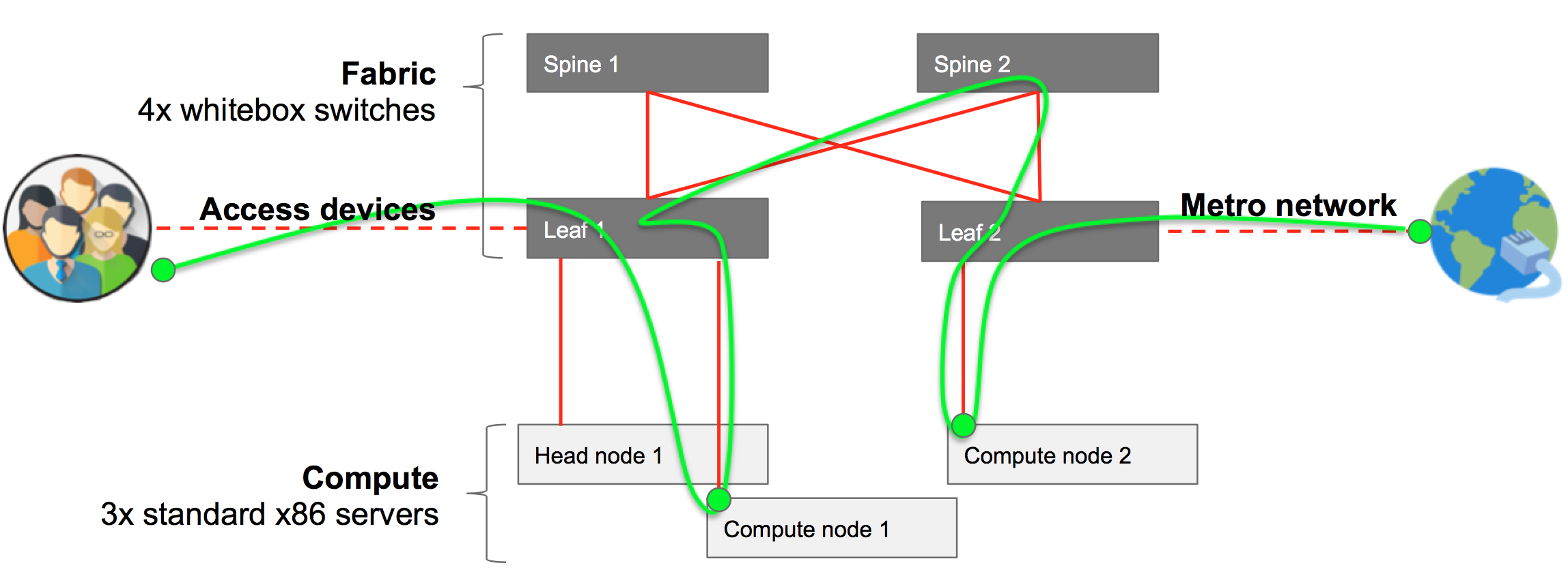
The fabric switches form a classic leaf and spine topology. A typical POD has two leafs and two spines.
At the moment, this is a pure 40G network.
While spines are not connected together, each leaf is connected to both spines.
In summary, the following are the devices connecting to the leaf switches:
Head node - 1x 40G interface
Compute node 1 - 1x 40G interface
Compute node 2 - 1x 40G interface
Access devices - 1 or more 40G interfaces
Metro devices - 1 or more 40G interfaces
Best-practice
The community follows a set of best rules to better be able to remotely debug issues, for example via mailing-lists. The following is not mandatory to be followed, but strongly suggested:
Leaf nodes are connected to the spines nodes starting at the highest port number on the leaf.
For a given leaf node, its connections to the spine nodes terminate on the same port number on each spine.
Leaf n connections to spine nodes terminate at port n on each spine node.
Leaf spine switches are connected into the management TOR starting from the highest port number.
Compute node n connects to the internal (management) network switch on port n.
Compute node n connects to its leaf at port n.
Head node connects to the internal (management) network using the lowest 1G management interface.
The head node connects to the external network using its highest 1G management interface.
All servers connect to the leafs using the lowest fabric (40G NIC) interface.