Following is a brief description of a generic full POD.
Physical representation
Usually, a typical full cord POD includes a ToR management switch, four fabric switches and three standard x86 servers.
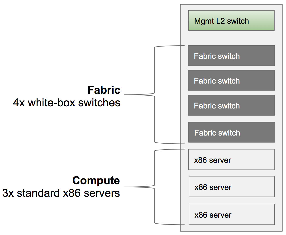
The picture doesn’t show devices for the access and the upstream connectivity to the metro network, reported instead in the picture below.
Logical representation - the data plane network
The diagram is a high level logical representation of a typical CORD POD.
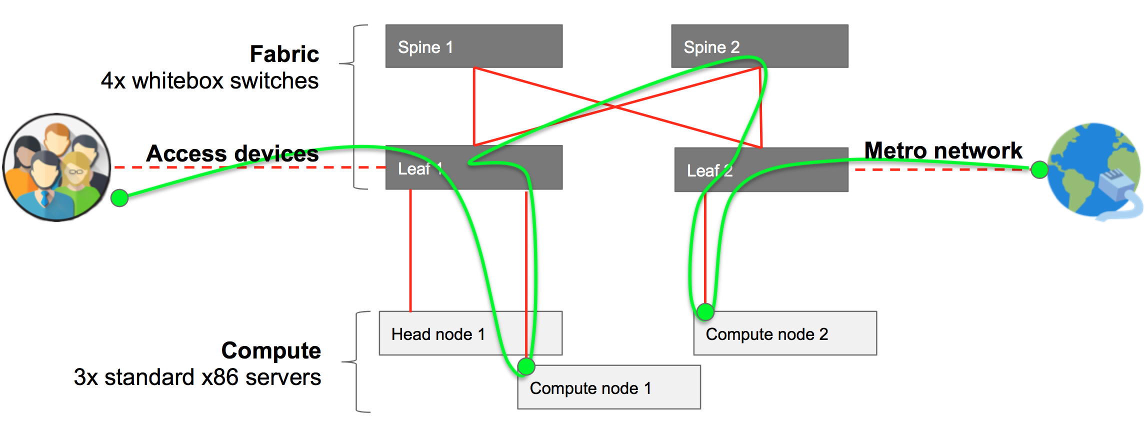
It shows in red the 40G data plane connections. The end-user traffic going from the access devices to the metro network, is shown in green. User (data plane) traffic goes through different different leafs, spines and compute nodes, depending on the services needed, and where they are located.
The switches form a leaf and spine fabric. The compute nodes and the head node are connected to a port of one of the leaf switches.
Logical representation - the control plane / management network
The diagram shows in blue how the components of the system are connected through the management network.
