Bill of Materials
The quickest way to get a deployment going is by starting with the BOM.
Overview
The E-CORD "pod" is multiple CORD sites (pods) connected by some transport network. The former can be a typical CORD site comprised of a head node, one or more compute nodes, and one or more fabrics. The latter, which provides connectivity between the CORD sites, can be almost anything, from an optical network requiring a converged view of the logical layers, to a single packet switch. The transport network has the possibility of being composed of white-boxes, legacy equipment, or a mix of both.
The remainder of this page will describe one approach to deploying a E-CORD pod, using the ON.Lab deployment as an example.
CORD
Site Deployment
CORD sites are deployed by roughly following quickstart_physical. The high-level procedure for deploying a CORD site is as follows:
- Set up a CORD build Vagrant VM. This VM, named corddev, is where all required bits are downloaded and built, with the help of a series of Ansible scripts invoked using Gradle. The host of this VM is the build machine, typically a laptop, or maybe an additional machine in the rack not being used as part of the CORD site.
- Fetch and build the Docker images and registry onto the build VM.
- Publish the images on the build VM to the designated CORD head node. This sets a registry up on the head node.
- Edit the pod configuration file, specifying the target head node IP, address blocks to use for the CORD site internally, and so on.
- Set up MAAS and XOS on the head node. The build process, like the other steps, is initialized from the build VM. This step will mangle the network configurations on the head node to fit the site organization for CORD. This step will set the head node up as a PXE/DHCP/DNS server for managing the compute node(s) and switch(es) within one CORD site.
- PXE boot the compute node(s) and fabric switch(es) against the head node. This step will do a fresh reinstall of the node(s)/switch(es), and configures the network on the devices so that they logically reside within the CORD site management network.
- Set up fabric configurations and connect the switch(es) to the ONOS instance for managing the fabric. Likewise set up the XOS/CORD ONOS as appropriate (in the quickstart, this would be the VTN app).
The ON.Lab Deployment
Overview
The E-CORD pod will contain three CORD sites connected by one transport node (packet switch). Each site is essentially a central office. In the E-CORD pod, each site is a half-pod, which contains:
- 1 fabric switch
- 1 head node
- 1 compute node
The pod also includes an additional node which will run the global orchestrator components, indirectly connected to the CORD sites and transport switch through the management network. Note that there are two different management network types:
- The rack management network, accessible from the office testbed network, and
- The CORD management networks, one per site and used by the head node to manage its corresponding compute and fabric nodes. From the rack management network, these are configured as VLANs at the top of rack switch so that the traffic doesn't logically leak into the testbed network.
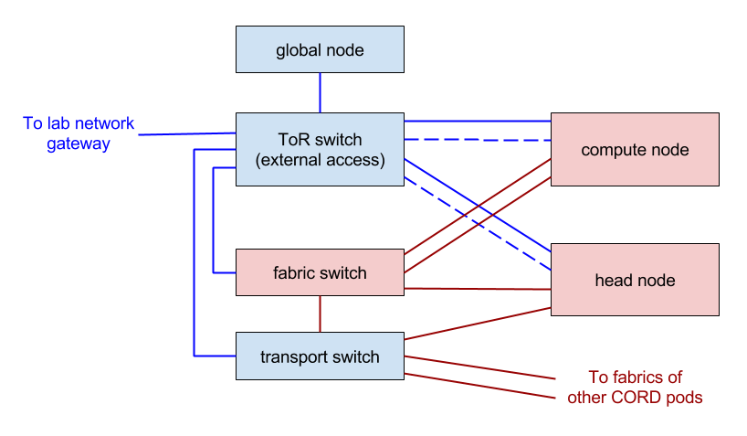
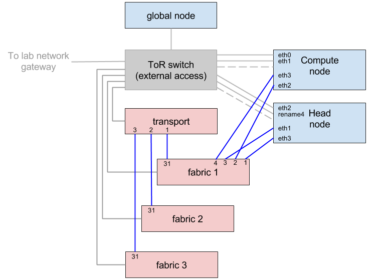
Logical Topology
The deployment scripts for CORD assume that the compute and head nodes have four interfaces, two 1GBe, and two 40GBe. It also assumes that each has a particular role, and will rewrite the interfaces file (in Ubuntu), in order to configure them to fit that role. How the interfaces are configured is itself guided by the pod configuration YAML file.
The following is a diagram that attempts to summarize the logical and physical network configurations for one half pod, and how it connects to the ToR switch and global node. Only the configurable pieces that can be gleaned from the interfaces file and brctl are shown.
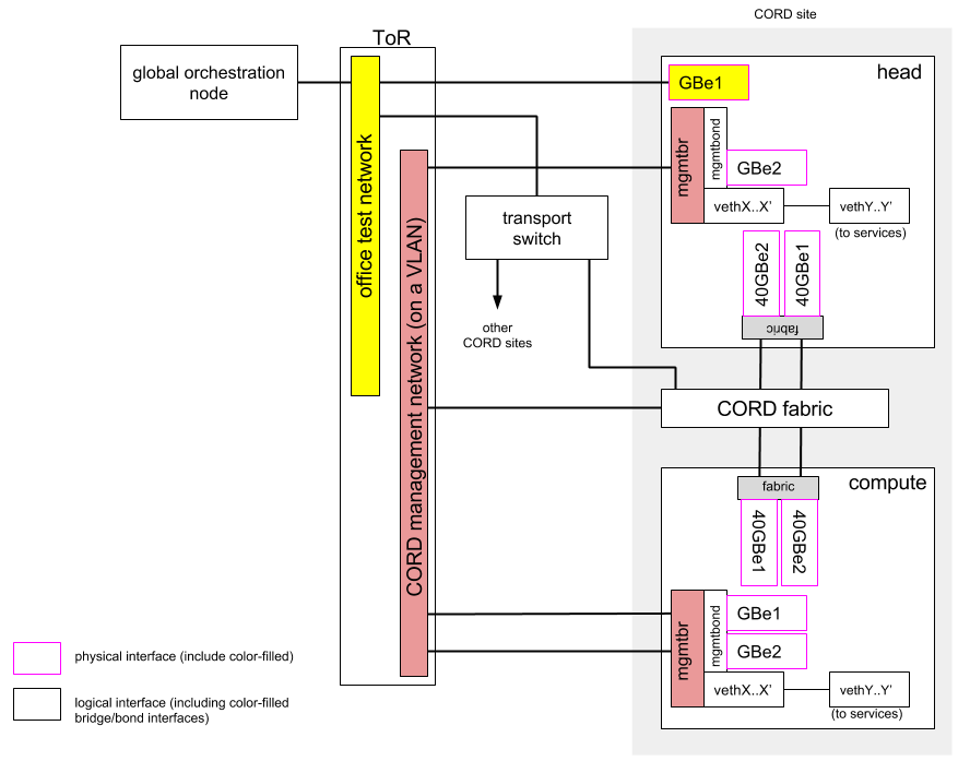
The Head Node
Once a CORD site is set up according to quickstart_physical, the head node will be running a series of Docker containers and VMs that are part of the various CORD and XOS services. It will have three Linux bridges:
- docker0 - docker registry and maven repo containers
- br-<6-byte string> - CORD (MAAS, provisioner, dhcp-harvester, etc) containers
- mgmtbr - XOS component VMs (openstack, XOS, ONOS instances, ceilometer, etc)
Of the three, mgmtbr incorporates a bond, mgmtbond, that in turn one of the 1GBe interfaces (GBe2 above) are part of. This interface will be used by services like MAAS to bootstrap compute nodes and switches, and is the CORD management plane -facing interface of the head node. Since the services include things like DHCP, and expects its own address block, mgmtbr is connected to a VLAN just for the particular site.
Also connected to mgmtbr are the virtual Ethernet links exposing the services hosted on the head node to the management network.
The other 1GBe interface is the outside (WAN) -facing interface not associated with any bridge devices, and is the means for accessing the head node (and the rest of the site's devices) from the outside world. Hence, it connects to the office network.
The 40GBe interfaces are bonded together and connected to the fabric switch. Note that in the head node, these fabric interfaces are not used.
The Compute Node
The one compute node of a half-pod is booted off of the MAAS service running on the head node. Since the compute node is confined to the CORD management network, both of its GBe interfaces are bonded together and attached to mgmtbr. The head node of a CORD site is the entry point to reach the rest of the nodes of a site, including the compute node and the management shell of the fabric switch.
The Global node
The global node interacts with the head node of each site and the transport network, so it connects to the office network along with the transport switch.
Global Head Node
You will need to install the Docker Engine as well as Docker Compose on the machine that will function as global head node. Refer to the Docker documentation for further instructions.
This node is a simplified XOS install, in that it does not require any OpenStack components nor the OpenStack synchronizer. As described in the XOS install guide (https://github.com/open-cloud/xos/tree/master/containers), all that's needed are the PostgreSQL and XOS Docker containers. You can easily build them yourself by cloning the XOS repo and generating the Docker containers as below.
$ git clone https://gerrit.opencord.org/xos
$ cd xos/containers
$ cd postgresql; make build; cd -
$ cd xos; make build; cd -
To run the images, we use Docker Compose with a customized YAML file, which is basically the same as docker-compose.yml with everything commented out except the xos-db (db refers to the PostgreSQL database) and xos containers. Save this new file using any name you like, we use ecord-global.yml.
$ docker-compose -f ecord-global.yml up -d
Testing (incomplete)
Currently, the topology is incomplete, which limits the range of testing that can be done.
- Fabric ping tests
- VTN Manual Tests
Fabric ping tests
The fabric/40G portion of the topology is modified as follows (highlighted in dark red):
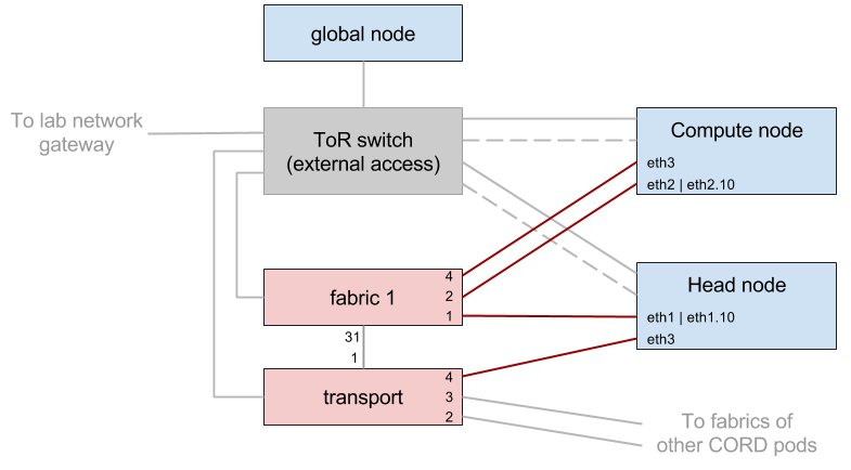
The fiber links on the head node (if1 and if2), aren't used under normal CORD pod operation, so are re-purposed as source and sink for test traffic. The sink represents an endpoint in another CORD site across the transport network. The complete traffic path in this test case is:
                    (cross connect)                                 (outbound)
[head node|eth1] --> [1|fabric 1|2] --> [eth2|compute node|eth2] --> [2|fabric 1|31] --> [1|transport|4] --> [eth3|head node]

#[a|foo|b] : node 'foo', with input port 'a' and output 'b'
The fabric node is traversed twice, for the cross connect into the compute node and outwards towards the remote CORD site. The path can be split into two smaller paths, 1) head node to compute node through the cross-connect, and 2) compute node to head node via the transport.
1) head node to compute node
The changes in addition to the wiring are:
- Decoupling of the bonded fabric interfaces - The bonding is commented out in interfaces(5), then fabric and bond interfaces are taken down and brought back up with
ifupandifdownto apply the changes. - Assignment of VLAN IDs to interfaces - VLAN interfaces are created on eth1 of the head node and eth2 on the compute node (the port connected to the location specified in the "hosts" clause of the fabric configuration file - in this case, port 2 of fabric 1) and assigned matching VLAN IDs (arbitrarily 10 here).
A VLAN cross connect configuration section is added to the fabric configuration file. For the topology shown, the added configuration is:
  "apps" : {
    "org.onosproject.segmentrouting" : {
      "xconnect" : {
        "of:0000cc37ab7cc2fa" : [ {
          "vlan" : 10,
          "ports" : [ 1, 2 ],
          "name" : "s1xc1"
        } ]
      }
    }
  }
Where of:0000cc37ab7cc2fa is the DPID of fabric 1, [1, 2] the ports connected to the VLANned interfaces of the head and compute nodes, respectively, and 10 is the aforementioned VLAN ID. The name "s1xc1" is arbitrary. Once this file is pushed to onos-fabric, and the VLAN interfaces are assigned IP addresses, it should be possible to ping between the head and compute nodes.
For pushing the configuration file, following the steps in quickstart_physical should suffice, but if it doesn't, pushing the file manually from the XOS VM should also work, e.g.:
$ curl --user karaf:karaf -X POST -H "Content-Type: application/json" http://onos-fabric:8181/onos/v1/network/configuration/ -d @/home/ubuntu/xos_services/fabric/config/network-cfg-quickstart.json