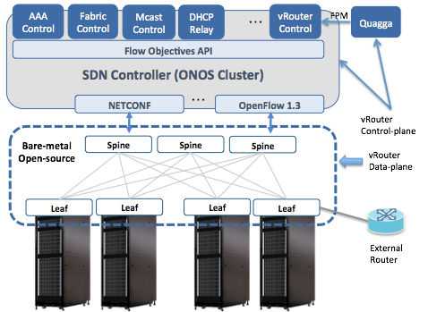
The Trellis fabric needs to be connected to the external world via the vRouter functionality. In the networking industry, the term vRouter implies a "router in a VM". This is not the case in Trellis.
The Trellis vRouter is NOT a software router. Only the control plane of the router – i.e routing protocols – run in a VM. We use the Quagga routing protocol suite as the control plane for vRouter.
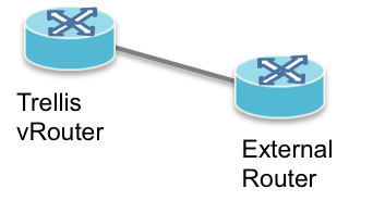
The vRouter dataplane is entirely in hardware - essentially the entire hardware fabric serves as the (distributed) dataplane for vRouter. The external router views the entire network infrastructure as a single router.
Physical Connectivity
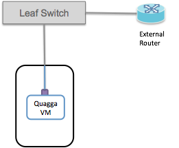
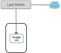
External routers must be physically connected to one of the fabric leaf switches. Currently there is a limitation that the external/upstream router and the Quagga instance must be connected to the same fabric leaf switch.
Therefore it is necessary to use an additional front panel port on the leaf-switch (or at least an additional vlan) to connect to the compute node hosting Quagga.
Switchport Configuration
We currently support BGP for external connectivity. In some cases, we can support OSPF and IS-IS as well.
The operator will need to configure a subnet between the Leaf-switch, the external/upstream router and the Quagga instance. There are 3 IP addresses we need to allocate - 1 on the switchports, 1 in Quagga, and 1 on the upstream router. This means the peering subnet cannot be smaller than a /29.
BGP peering happens between the IP addresses configured on the interfaces in Quagga and the external router.
Routes are advertised by Quagga to the upstream with the next-hop set to the switchport IP address. This means that when traffic comes to the fabric leaf switch from outside, the switch is able to distinguish peering traffic from data traffic and treat each appropriately.
An example of how this is configured is shown in the following figure:

In this case the peering subnet is 10.0.1.0/24. The upstream router is using the 10.0.1.1 address. Quagga is assigned 10.0.1.3, which is the address used for peering. The upstream router needs to be configured with 10.0.1.3 as its BGP neighbor, and the BGP peering will be established between 10.0.1.1 and 10.0.1.3.
The 10.0.1.2 address is used by the fabric switch and for the next-hop for routes advertised by Quagga.
Of course you are not obliged to use 10.0.1.0/24, you should use a subnet that makes sense for your peering environment.
The following shows a configuration example:
{
    "ports" : {
        "of:0000000000000001/1" : {
            "interfaces" : [
                {
                    "name" : "upstream1",
                    "ips"  : [ "10.0.1.2/24" ],
                    "vlan-untagged" : 4000
                }
            ]
        },
        "of:0000000000000001/2" : {
            "interfaces" : [
                {
                    "name" : "quagga",
                    "ips"  : [ "10.0.1.2/24" ],
                    "vlan-untagged" : 4000
                }
            ]
        }
    }
}
- name - an arbitrary name string for the interface
- ips - configure the peering subnet (10.0.1.0/24) and the switchport IP (10.0.1.2). Note that we use the same IP address on both the quagga and upstream interfaces.
- vlan-untagged - configure the same VLAN ID on both interfaces. It doesn't matter exactly what the VLAN ID is, but it must be the same on both the quagga-facing and upstream-facing interfaces.
This configuration will set up an L2 link between the two fabric switch ports, over which the Quagga and external router can communicate. Both Quagga and the upstream router will receive untagged packets (i.e they will never see packets with vlanId 4000, which is used inside the leaf switch to establish a bridging domain). Note that if you need a vlan-tag in the compute node to distinuguish the traffic going to Quagga, you can change the vlan assignment on the switchport "of:0000000000000001/2" to be vlan-tagged instead of vlan-untagged.
Deploy the Quagga Docker Image
Download the image and pipework
CORD uses a slightly modified version of Quagga, so the easiest way to deploy this is to use the provided docker image.
docker pull opencord/quagga
We also need to download the pipework tool which will be used to connect the docker image to the physical interface that we set aside earlier.wget https://raw.githubusercontent.com/jpetazzo/pipework/master/pipework chmod +x pipework
Create a directory for your Quagga configuration files, and create a bgpd.conf and zebra.conf in there. More on configuring Quagga later.
mkdir configs
Now run the docker image (make sure the path the config directory matches what is on your system):
sudo docker run --privileged -d -v configs:/etc/quagga -n quagga opencord/quagga
Finally, we can use the pipework tool to add the physical interface into the container so that Quagga can talk out over the fabric:
sudo ./pipework mlx1 -i eth1 quagga 10.0.1.3/24
This will add host interface mlx1 to the container with name quagga with interface name eth1 inside the container. The newly added interface will have the IP 10.0.1.3. This IP address should be the peering subnet address that you want to assign to Quagga.
If you need to change anything about the container (for example if you change the Quagga configuration) you can remove the original container and run a new one:
docker rm -f quagga
sudo docker run --privileged -d -v configs:/etc/quagga -n quagga opencord/quagga
Configure Quagga
At this point Quagga should have IP connectivity to the external routers, and it should be able to ping them on the peering subnet.
Now Quagga and the upstream routers can be configured to peer with one another. This configuration of Quagga is going to be highly dependent on the configuration of the upstream network, so it won't be possible to give comprehensive configuration examples here. It is recommended to consult the Quagga documentation for exhaustive information on Quagga's capabilities and configuration. Here I will attempt to provide a few basic examples of Quagga configuration to get you started. You'll have to enhance these with the features and functions that are needed in your network.
Zebra Configuration
Regardless of which routing protocols you are using in your network, it is important to configure Zebra's FPM connection to send routes to the vRouter app running on ONOS. This feature was enabled by the patch that was applied earlier when we installed Quagga.
A minimal Zebra configuration might look like this:
!
hostname cord-zebra
password cord
!
fpm connection ip 10.6.0.1 port 2620
!
The FPM connection IP address is the IP address of one of the onos cluster instances - does not matter which one.
If you have other configuration that needs to go in zebra.conf you should add that here as well.
BGP configuration
An example simple BGP configuration for peering with one BGP peer might look like this:
hostname bgp
password cord
!
ip prefix-list 1 seq 10 permit 192.168.0.0/16
!
route-map NEXTHOP permit 10
match ip address prefix-list 1
set ip next-hop 10.0.1.2
!
router bgp 65535
  bgp router-id 10.0.1.3
  !
  network 192.168.0.0/16
  !
  neighbor 10.0.1.1 remote-as 65540
  neighbor 10.0.1.1 description upstream1
  neighbor 10.0.1.1 route-map NEXTHOP out
  !
This configuration peers with one upstream router (10.0.1.1) and advertises one route (192.168.0.0/16). Note that Quagga (and as a result Trellis) is in a different AS (65535) from the upstream router (AS 65540), as we are using E-BGP for this connectivity.
Pay attention to the configuration to rewrite the next hop of routes that are advertised to the upstream router. A route-map is used to set the next hop of advertised routes to 10.0.1.2, which is different from the address that Quagga is using to peer with the external router. As mentioned above, it is important that this rewriting is done correctly so that the fabric switch is able to distinguish data plane and control plane traffic.