Introduction to OFDPA Pipeline
In this design note, we are going to explain the design choices we have made and how we got around OFDPA (OpenFlow Data Plane Abstraction) pipeline restrictions to implement the features we need.
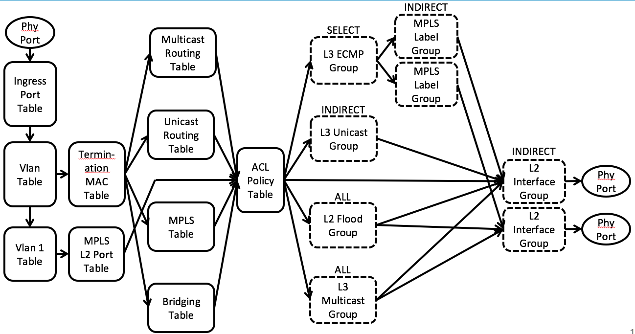
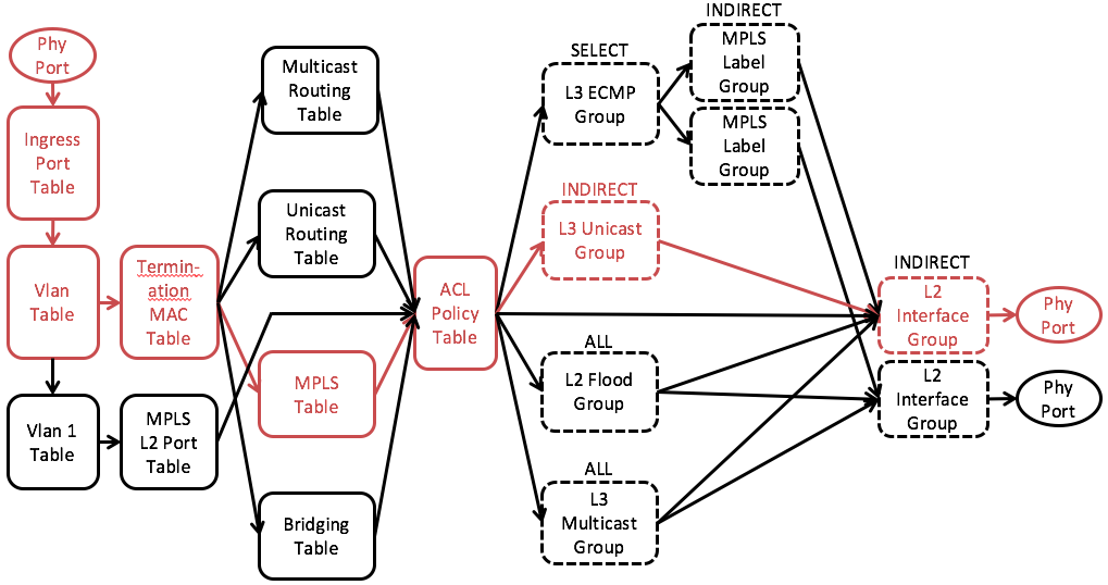
We will start from explaining the OFDPA flow tables and group tables we use. Fig. 1 shows the simplified OFDPA pipeline overview.
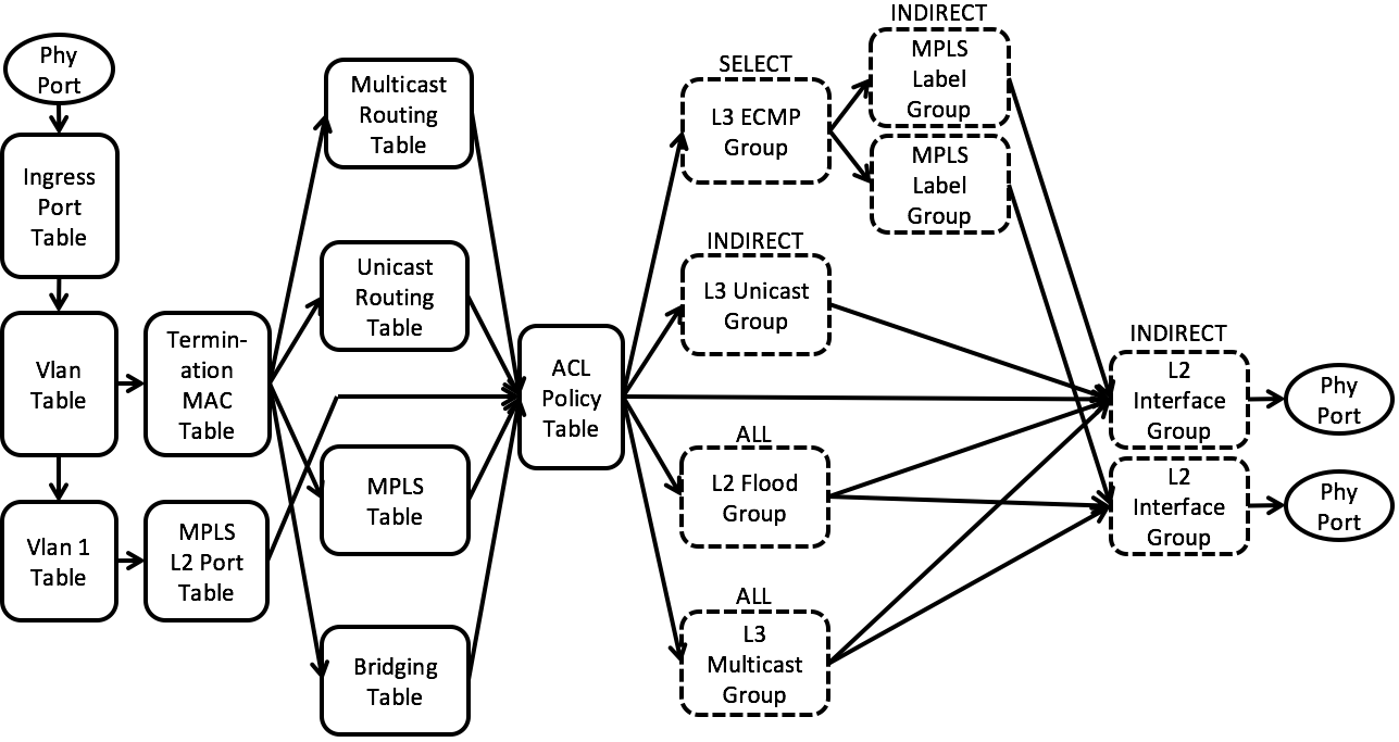
Fig. 1 Simplified OFDPA pipeline overview
Flow Tables
VLAN Table
The VLAN Flow Table is used for IEEE 801.Q VLAN assignment and filtering to specify how VLANs are to be handled on a particular port.22 All packets must have an associated VLAN id in order to be processed by subsequent tables.
Packets that do not match any entry in the VLAN table will goto ACL table
According to OFDPA spec, we need to assign a VLAN ID even for untagged packets. Each untagged packet will be tagged with an internal VLAN when being handled by VLAN table. The internal VLAN will be popped when the packet is sent to a output port or controller.
The internal VLAN is assigned according to the subnet configuration of the input port. Each subnet will be assigned for a VLAN ID, starting from 4093 and descending. Packets coming from ports that do not have subnet configured (e.g. the spine facing ports) will be tagged with VLAN ID 4094.
The internal VLAN is also used to determine the subnet when a packet needs to be flooded to all ports in the same subnet. (See L2 Broadcast section for detail.)
Termination MAC (TMAC) Table
The Termination MAC Flow Table determines whether to do bridging or routing on a packet. It identifies routed packets their destination MAC, VLAN, and Ethertype. Routed packet rule types use a Goto-Table instruction to indicate that the next table is one of the routing tables.
The default on a miss is the Bridging Flow Table.
In this table, we determine which table the packet should go to by checking the destination MAC address and the ethernet type of the packet.
- if dst_mac = router MAC and eth_type = ip, goto unicast routing table
- if dst_mac = router MAC and eth_type = mpls, goto mpls table
- if dst_mac = multicast MAC (01:00:5F:00:00:00/FF:FF:FF:80:00:00), goto multicast routing table
- none of above, goto bridging table
Unicast Routing Table
Default next table on miss is the ACL Policy Flow Table.
In this table, we determine where to output a packet by checking its destination IP (unicast) address.
- if dst_ip locates at a remote switch, the packet will go to an L3 ECMP group, be tagged with MPLS label, and further go to a spine switch
- if dst_ip locates at the same switch, the packet will go to an L3 interface group and further go to a host
Note that the priority of flow entries in this table is sorted by prefix length. Longer prefix (/32) will have higher priority than shorter prefix (/0).
Multicast Routing Table
Flow entries in this table always match the destination IP (multicast). Matched packets will go to an L3 multicast group and further go to the next switch or host.
MPLS Table
The MPLS pipeline can support three MPLS Flow Tables, MPLS Table 0, MPLS Table 1 and MPLS Table 2. An MPLS Flow Table lookup matches the label in the outermost MPLS shim header in the packets. MPLS Table 0 is only used to pop a protection label on platforms that support this table, or to detect an MPLS- TP Section OAM PDU. MPLS Table 1 and MPLS Table 2 can be used for all label operations. MPLS Table 1 and MPLS Table 2 are synchronized flow tables and updating one updates the other
Default next table on miss is the ACL Policy Flow Table.
We only use MPLS Table 1 (id=24) in current design. MPLS packets are matched by the MPLS label. The packet will go to L3 interface group with MPLS label being popped and further go to destination leaf switch.
Bridging Table
The Bridging Flow Table supports Ethernet packet switching for potentially large numbers of flow entries using the hardware L2 tables. The default on a miss is to go to the Policy ACL Flow Table.
The Bridging Flow Table forwards either based on VLAN (normal switched packets) or Tunnel id (isolated forwarding domain packets), with the Tunnel id metadata field used to distinguish different flow table entry types by range assignment.
Default next table on miss is the ACL Policy Flow Table.
In this table, we match the VLAN ID and the destination MAC address and determine where the packet should be forwarded to.
- If the destination MAC can be matched, the packet will go to the L2 interface group and further sent to the destination host.
- If the destination MAC can not be matched, the packet will go to the L2 flood group and further flooded to the same subnet.
Since we cannot match IP in bridging table, we use the VLAN ID to determine which subnet this packet should be flooded to. The VLAN ID can be either (1) the internal VLAN assigned to untagged packets in VLAN table or (2) the VLAN ID that comes with tagged packets.
Policy ACL Table
The Policy ACL Flow Table supports wide, multi-field matching. Most fields can be wildcard matched, and relative priority must be specified in all flow entry modification API calls. This is the preferred table for matching BPDU and ARP packets. It also provides the Metering instruction.
The default on table miss is to do nothing. The packet will be forwarded using the output or group in the action set, if any. If the action set does not have a group or output action the packet is dropped.
In ACL table we match ARP, LLDP and BDDP and send those packets to the controller.
Group Tables
L3 ECMP Group
OF-DPA L3 ECMP group entries are of OpenFlow type SELECT. For IP routing the action buckets reference the OF-DPA L3 Unicast group entries that are members of the multipath group for ECMP forwarding.
An OF-DPA L3 ECMP Group entry can also be used in a Provider Edge Router. In this packet flow it can chain to either an MPLS L3 Label group entry or to an MPLS Fast Failover group entry.
An OF-DPA L3 ECMP Group entry can be specified as a routing target instead of an OF-DPA L3 Unicast Group entry. Selection of an action bucket for forwarding a particular packet is hardware-specific.
MPLS Label Group
MPLS Label Group entries are of OpenFlow INDIRECT type. There are four MPLS label Group entry subtypes, all with similar structure. These can be used in different configurations to push up to three labels for tunnel initiation or LSR swap.
MPLS Interface Group
MPLS Interface Group Entry is of OpenFlow type INDIRECT. It is used to set the outgoing L2 header to reach the next hop label switch router or provider edge router.
We use L3 ECMP group to randomly pick one spine switch when we need to route a packet from leaves to spines.
We point each bucket to an MPLS Label Group in which the MPLS labels are pushed to the packets to realize Segment Routing mechanism. (More specifically, we use the subtype 2 MPLS L3 VPN Label.)
We then point an MPLS Label Group points to an MPLS Interface Group in which the destination MAC is set to the next hop (spine router.)
Finally, the packet will goto an L2 Interface Group and being sent to the output port that goes to the spine router.
Detail of how segment routing is implelmented will be explained in the L3 unicast section below.
L3 Unicast Group
OF-DPA L3 Unicast group entries are of OpenFlow INDIRECT type. L3 Unicast group entries are used to supply the routing next hop and output interface for packet forwarding. To properly route a packet from either the Routing Flow Table or the Policy ACL Flow Table, the forwarding flow entry must reference an L3 Unicast Group entry.
All packets must have a VLAN tag. A chained L2 Interface group entry must be in the same VLAN as assigned by the L3 Unicast Group entry.
We use L3 Unicast Group to rewrite the source MAC, destination MAC and VLAN ID when routing is needed.
L3 Multicast Group
OF-DPA L3 Multicast group entries are of OpenFlow ALL type. The action buckets describe the interfaces to which multicast packet replicas are forwarded.
Note that
(1) any chained OF-DPA L2 Interface Group entries must be in the same VLAN as the OF-DPA L3 Multicast group entry. However,
(2) chained OF-DPA L3 Interface Group entries must be in different VLANs from the OF-DPA L3 Multicast Group entry, and from each other.
We use L3 multicast group to replicate multicast packets when necessary. It is also possible that L3 multicast group consists of only one bucket when replication is not needed.
Detail of how multicast is implemented will be explained in the L3 multicast section below.
L2 Interface Group
L2 Interface Group entries are of OpenFlow INDIRECT type, with a single action bucket.
OF-DPA L2 Interface group entries are used for egress VLAN filtering and tagging. If a specific set of VLANs is allowed on a port, appropriate group entries must be defined for the VLAN and port combinations.
Note: OF-DPA uses the L2 Interface group declaration to configure the port VLAN filtering behavior. This approach was taken since OpenFlow does not support configuring VLANs on physical ports.
L2 interface group can match on specific VLAN ID and decide whether or not to pop the VLAN before sending to an output port.
We pop the VLAN that was internally assigned to untagged packets and keep the VLAN that came with tagged packets.
In OFDPA, every above-mentioned group must be chained to a L2 interface group eventually before being sent to the output port.
L2 Flood Group
L2 Flood Group entries are used by VLAN Flow Table wildcard (destination location forwarding, or DLF) rules. Like OF-DPA L2 Multicast group entry types they are of OpenFlow ALL type. The action buckets each encode an output port. Each OF-DPA L2 Flood Group entry bucket forwards a replica to an output port, except for packet IN_PORT.
All of the OF-DPA L2 Interface Group entries referenced by the OF-DPA Flood Group entry, and the OF- DPA Flood Group entry itself, must be in the same VLAN.
Note: There can only be one OF-DPA L2 Flood Group entry defined per VLAN.
Assumptions
Here are some assumptions we have made.
- There can be at most one subnet configured on one leaf switch port.
- One subnet cannot be configured on multiple leaf switches. (We usually configure one subnet for all the ports on the same leaf switch.)
L2 Unicast

Fig. 2 L2 Unicast

Fig. 3 Simplified L2 Unicast pipeline
The L2 unicast mechanism is designed to support intra-rack (intra-subnet) untagged communication when the destination host is known.
Pipeline walkthrough:
VLAN Table: An untagged packet will be assigned an internal VLAN ID according to the input port and the subnet configured on the input port. Packets of the same subnet will have the same internal VLAN ID.
TMAC Table: Since the destination MAC of a L2 unicast packet is not the MAC of leaf router, the packet will miss the TMAC table and goes to the bridging table.
Bridging Table: If the destination MAC is learnt, there will be a flow entry matching that destination MAC and pointing to an L2 interface group.
ACL Table: IP packets will miss the ACL table and the L2 interface group will be executed.
L2 Interface Group: The internal assigned VLAN will be popped before the packet is sent to the output port.
L2 Broadcast
Fig. 4 L2 Broadcast
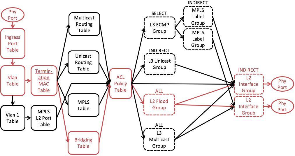
Fig. 5 Simplified L2 Broadcast Pipeline
The L2 broadcast mechanism is designed to support intra-rack (intra-subnet) untagged communication when the destination host is unknown.
Pipeline walkthrough (Fig. 5):
VLAN Table: (same as L2 unicast)
TMAC Table: (same as L2 unicast)
Bridging Table: If the destination MAC is not learnt, there will NOT be a flow entry matching that destination MAC. It will then fallback to a lower priority entry that matches the VLAN (subnet) and point to an L2 flood group.
ACL Table: IP packets will miss the ACL table and the L2 flood group will be executed.
L2 Flood Group: Consists of all L2 interface groups related to this VLAN (subnet).
L2 Interface Group: The internal assigned VLAN will be popped before the packet is sent to the output port.
ARP
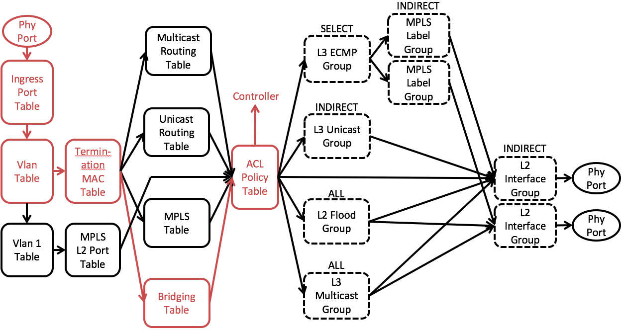
Fig. 6 Simplified ARP Pipeline
All ARP packets will be sent to the controller and Segment Routing will do proxy ARP.
ARP Request:
- For ARP request asking router IP, send an ARP reply with router MAC.
- For ARP request asking a known host, send an proxy ARP on behalf of the target host.
- For ARP request asking an unknown host, flood the packet to all ports in the same subnet.
ARP Reply:
- For ARP reply going to router, process all IP packets waiting for the next hop MAC address.
- For ARP reply going to known host, forward to the host.
- For ARP reply going to unknown host, flood the packet to all ports in the same subnet.
Pipeline walkthrough:
It is similar to L2 broadcast. Except ARP packets will be matched by a special ACL table entry and being sent to the controller instead of the output groups.
L3 Unicast
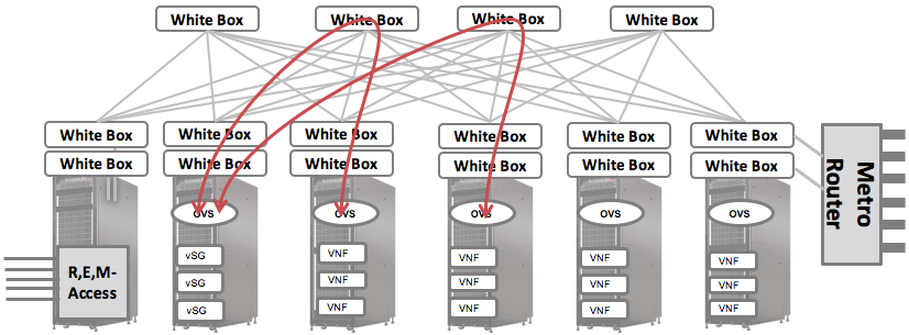
Fig. 7 L3 Unicast
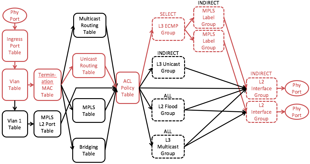
Fig. 8 Simplified L3 Unicast Pipeline - Source Leaf

Fig. 9 Simplified L3 Unicast Pipeline - Spine
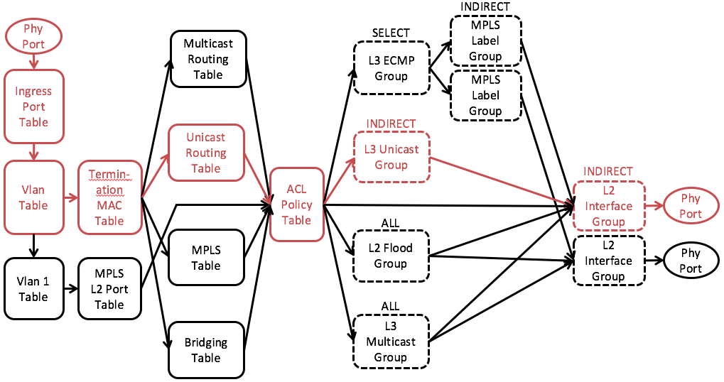
Fig. 10 Simplified L3 Unicast Pipeline - Destination Leaf
The L3 unicast mechanism is designed to support inter-rack(inter-subnet) untagged communication when the destination host is known.
IPv6 Not Supported
Only IPv4 is supported at this moment.
Reserved MPLS labels
We should avoid using reserved MPLS labels. Please check here for the reserved values: http://www.iana.org/assignments/mpls-label-values/mpls-label-values.xhtml
Host Learning Not Supported
Host learning is not supported due to the restriction of current OFDPA version (i12_1.7). This should be fixed as soon as we move to the latest version (GA 2.0.) Please refer to Fabric Configuration Guide (ONOS 1.8) to see how to configure a host.
Path Calculation and Failover:
Coming soon...
Pipeline walkthrough - Source Leaf Switch (Fig. 8):
VLAN Table: An untagged packet will be assigned an internal VLAN ID according to the input port and the subnet configured on the input port. Packets of the same subnet will have the same internal VLAN ID.
TMAC Table: Since the destination MAC of a L3 unicast packet is the MAC of leaf router and the ethernet type is IPv4, the packet will match the TMAC table and go to the unicast routing table.
Unicast Routing Table: In this table we will lookup the destination IP of the packet and point the packet to corresponding L3 ECMP group
ACL Table: IP packets will miss the ACL table and the L3 ECMP group will be executed.
L3 ECMP Group: Hashes on 5 tuple to pick a spine switch and goto the MPLS Label Group.
MPLS Label Group: Push the MPLS label corresponding to the destination leaf switch and goto the MPLS Interface Group.
MPLS Interface Group: Set source MAC address, destination MAC address, VLAN ID and goto the L2 Interface Group.
L2 Interface Group: The internal assigned VLAN will be popped before the packet is sent to the output port that goes to the spine.
Pipeline walkthrough - Spine Switch (Fig. 9):
VLAN Table: An untagged packet will be assigned an internal VLAN ID according to the input port and the subnet configured on the input port. Packets of the same subnet will have the same internal VLAN ID.
TMAC Table: Since the destination MAC of a L3 unicast packet is the MAC of spine router and the ethernet type is MPLS, the packet will match the TMAC table and go to the MPLS table.
MPLS Table: In this table we will lookup the MPLS label of the packet, figure out the destination leaf switch, pop the MPLS label and point to L3 ECMP Group.
ACL Table: IP packets will miss the ACL table and the MPLS interface group will be executed.
L3 ECMP Group: Hash to pick a link (if there are multiple links) to the destination leaf and goto the L3 Interface Group.
MPLS Interface Group: Set source MAC address, destination MAC address, VLAN ID and goto the L2 Interface Group.
L2 Interface Group: The internal assigned VLAN will be popped before the packet is sent to the output port that goes to the destination leaf switch.
Pipeline walkthrough - Destination Leaf Switch (Fig. 10):
VLAN Table: An untagged packet will be assigned an internal VLAN ID according to the input port and the subnet configured on the input port. Packets of the same subnet will have the same internal VLAN ID.
TMAC Table: Since the destination MAC of a L3 unicast packet is the MAC of leaf router and the ethernet type is IPv4, the packet will match the TMAC table and go to the unicast routing table.
Unicast Routing Table: In this table we will lookup the destination IP of the packet and point the packet to corresponding L3 Unicast Group.
ACL Table: IP packets will miss the ACL table and the L3 Unicast Group will be executed.
L3 Unicast Group: Set source MAC address, destination MAC address, VLAN ID and goto the L2 Interface Group.
L2 Interface Group: The internal assigned VLAN will be popped before the packet is sent to the output port that goes to the destination leaf switch.
L3 Multicast
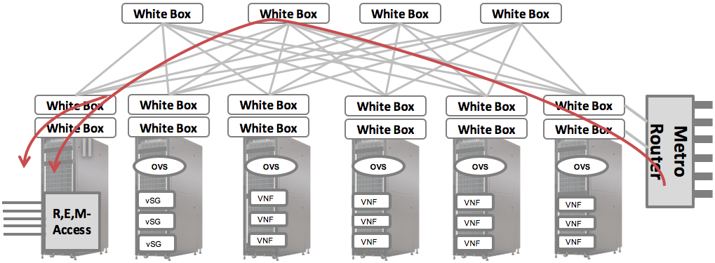
Fig. 11 L3 Multicast

Fig.12 Simplified L3 Multicast Pipeline
The L3 multicast mechanism is designed to support use cases such as IPTV. The multicast traffic comes in from the upstream router, replicated by the leaf-spine switches, send to multiple OLTs and eventually get to the subscribers.
Limited Topology
Only leaf-spine topology is supported by current multicast design.
Multicast groups addresses
Restriction and Solution:
We would like to support different combinations of ingress/egress VLAN, including
- untagged in -> untagged out
- untagged in -> tagged out
- tagged in -> untagged out
- tagged in -> same tagged out
- tagged in -> different tagged out
However, due to the above-mentioned OFDPA restrictions,
(1) It is NOT possible to chain L3 multicast group to L2 interface group directly if we want to change the VLAN ID
(2) It is NOT possible to change VLAN ID by chaining L3 multicast group to L3 interface group since all output ports should have the same VLAN but the spec requires chained L3 interface group to have different VLAN ID from each other.
That means, if we need to change VLAN ID, we need to change it before the packets get into the multicast routing table. The only viable solution is changing the VLAN ID in the VLAN table.
We change the VLAN tag on the ingress switch (i.e. the switch that connects to the upstream router) when necessary. On transit (spine) and egress (destination leaf) switches, output VLAN tag will remain the same as input VLAN tag.
Path Calculation and Failover:
Coming soon...
Pipeline walkthrough - Ingress Leaf Switch (Fig. 12):
| # | Input | VLAN Table | L3 Multicast Group | L2 Interface Group | Output |
|---|---|---|---|---|---|
| 1 | None | Set 4094 (*) | Match 4094 (*) | Pop VLAN | None |
| 2 | None | Set 200 | Match 200 | - | 200 |
| 3 | 200 | - | Match 200 | Pop VLAN | None |
| 4 | 200 | - | Match 200 | - | 200 |
| 5 | 200 | Set 300 | Match 300 | - | 300 |
Table 1. All Possible VLAN Combinations on Ingress Switch
(*) Note: In the presence of vlan-untagged configuration on the ingress port of the ingress switch, the vlan-untagged will be used instead of 4094. The reason is that we cannot distinguish unicast and multicast traffic in that case, and therefore must assign the same VLAN to the packet. The VLAN will anyway get popped in L2IG in this case.
Table 1 shows all possible VLAN combinations on the ingress switches and how the packet is processed through the pipeline. We take the second case (untagged -> tagged 200) as an example to explain more details.
VLAN Table: An untagged packet will be assigned the egress VLAN ID.
TMAC Table: Since the destination MAC of a L2 unicast packet is a multicast MAC address, the packet will match the TMAC table and goes to the multicast routing table.
Multicast Routing Table: In this table we will lookup the multicast group (destination multicast IP) and point the packet to the corresponding L3 multicast group.
ACL Table: Multicast packets will miss the ACL table and the L3 multicast group will be executed.
L3 Multicast Group: The packet will be matched by egress VLAN ID and forwarded to multiple L2 interface groups that map to output ports.
L2 Interface Group: The egress VLAN will be kept in this case and the packet will be sent to the output port that goes to the transit spine switch.
Pipeline walkthrough - Transit Spine Switch and Egress Leaf Switch (Fig. 11):
| # | Input | VLAN Table | L3 Multicast Group | L2 Interface Group | Output |
|---|---|---|---|---|---|
| 1 | None | Set 4094 | Match 4094 | Pop VLAN | None |
| 2 | 200 | - | Match 200 | - | 200 |
Table 2. All Possible VLAN Combinations on Transit/Egress Switch
Table 2 shows all possible VLAN combinations on the transit/egress switches and how the packet is processed through the pipeline. Note that we have already changed the VLAN tag to the desired egress VLAN on the ingress switch. Therefore, there are only two cases on the transit/egress switches - either keep it untagged or keep it tagged. We take the first case (untagged -> untagged) as an example to explain more details.
VLAN Table: An untagged packet will be assigned an internal VLAN ID according to the input port and the subnet configured on the input port. Packets of the same subnet will have the same internal VLAN ID.
TMAC Table: (same as ingress switch)
Multicast Routing Table: (same as ingress switch)
ACL Table: (same as ingress switch)
L3 Multicast Group: The packet will be matched by internal VLAN ID and forwarded to multiple L2 interface groups that map to output ports.
L2 Interface Group: The egress VLAN will be popped in this case and the packet will be sent to the output port that goes to the egress leaf switch.
VLAN Cross Connect
Fig. 13 VLAN Cross Connect

Fig. 14 Simplified VLAN Cross Connect Pipeline
VLAN Cross Connect is originally designed to support Q-in-Q packets between OLTs and vSGs. The cross connect pair consists of two output ports. Whatever packet comes in on one port with specific VLAN tag will be sent to the other port.
Note that it can only cross connects two ports on the same switch. Pseudo wire, which has not been implemented yet, is required to connect ports across different switches.
We use L2 Flood Group to implement VLAN Cross Connect. The L2 Flood Group for cross connect only consists of two ports. The input port will be removed before flooding according to the spec and thus create exactly the desire behavior of cross connect.
Pipeline walkthrough (Fig. 14):
VLAN Table: When a tagged packet comes in, we no longer need to assign the internal VLAN. The original VLAN will be carried through the entire pipeline.
TMAC Table: Since the VLAN will not match any internal VLAN assigned to untagged packets, the packet will miss the TMAC table and goes to the bridging table.
Bridging Table: The packet will hit the flow rule that match the cross connect VLAN ID and being sent to corresponding L2 Flood Group.
ACL Table: IP packets will miss the ACL table and the L2 flood group will be executed.
L2 Flood Group: Consists of two L2 interface groups related to this cross connect VLAN.
L2 Interface Group: The original VLAN will NOT be popped before the packet is sent to the output port.
vRouter Integration

Fig. 15 vRouter Integration
Usually there will be a leaf router connected to the upstream router in order to talk to the Internet. This gateway router will be managed by vRouter app and the routes learned by vRouter will be installed on its Unicast Routing Table.
At this moment we don't support router dual homing, that is, only one leaf router will be the gateway router.
For packets going out to the Internet, we simply add one default route (0.0.0.0/0) on all leaf routers except gateway router and route all packets that doesn't match any internal subnet to the gateway router.
For packets coming in from the Internet, we create a per-host (/32) routing entry for each hosts (vSG basically) that need Internet access based on their attachment point.
Special Configuration
Since the gateway router is managed by vRouter app, we need some special configuration to tell Segment Routing not to interfere with vRouter. Please refer to Connecting the POD to Upstream Networks for details about the special configuration required to integrate Segment Routing with vRouter.
Pipeline walkthrough:
The pipeline is exactly as same as L3 unicast. We just install additional flow rules in the unicast routing table on each leaf routers.